Difference between revisions of "Clocks"
| Line 4: | Line 4: | ||
This is a good papercraft book on making a working clock: [http://www.amazon.com/gp/redirect.html?ie=UTF8&location=http%3A%2F%2Fwww.amazon.com%2FMake-Your-Working-Paper-Clock%2Fdp%2F0060910666%3Fie%3DUTF8%26s%3Dbooks%26qid%3D1202690782%26sr%3D8-1&tag=wwwnoahorg-20&linkCode=ur2&camp=1789&creative=9325 Make Your Own Working Paper Clock] | This is a good papercraft book on making a working clock: [http://www.amazon.com/gp/redirect.html?ie=UTF8&location=http%3A%2F%2Fwww.amazon.com%2FMake-Your-Working-Paper-Clock%2Fdp%2F0060910666%3Fie%3DUTF8%26s%3Dbooks%26qid%3D1202690782%26sr%3D8-1&tag=wwwnoahorg-20&linkCode=ur2&camp=1789&creative=9325 Make Your Own Working Paper Clock] | ||
| − | |||
| − | |||
| − | |||
| − | |||
== Some notes on a clock design == | == Some notes on a clock design == | ||
Latest revision as of 18:03, 10 February 2008
Contents
clock books
This is a good papercraft book on making a working clock: Make Your Own Working Paper Clock
Some notes on a clock design
It all started with gears! I have an interest in gears. Most clocks require gears, so why not build a clock?
It turns out that clocks don't use the same type of gears that most machines use. The easiest gears for an amateur to make are "lantern gears" or "cage gears".
But I wanted "real" gears -- involute gears. The Brock Engineering site has about the best explanation for what makes modern involute gears special: http://www.brockeng.com/mechanism/RackNPinion.htm
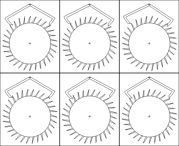
This was also an experiment in rapid model design that turned out to be not so rapid. I plan to build a clock from acrylic plastic. I have been using a LASER cutter to cut 1/4 Plexiglas. This first batch of gears was cut at Freedom Arts & Manufacturing, a LASER cutting service. The following picture shows a cutting plan for the LASER cutter to follow. Note that the voids that form the spokes of the largest gear are 16 tooth gears. This saves materials and makes an interesting spoke design. The figure at the lower right is an experimental escapement design that failed.
Philippe de La Hire was one of the first to suggest the epicycloidal profile for gear teeth. I find this form more pleasing than a traditional involute spur gear. I may use this form my clock design.
 |
|
On the left is a nine tooth cycloidal gear designed for me by Bob Kunkel of Roberts Engineering and Design in Albertville, Alabama. Bob also designed all my other gears.
Gear Train
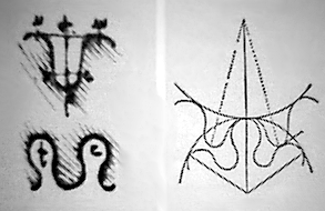
Gear ratios are chosen to convert the time counted by the escape wheel into minutes and hours. For a 30 tooth, 60 second escape wheel a 60:1 ratio is needed to count 60 minutes for one hour. Then to count 12 hours, a 12:1 ratio is needed. Below, the 9:78 and 13:90 gear train produces a 60:1 ratio. Note that the intermediate ratios are not integer values. It may seem more intuitive to choose a train with a 15:1 followed by a 4:1 to get 60:1, but a gear train with non-integer ratios will produce more even wear on the teeth over the lifetime of the clock. I wrote a program to search all gear combinations over a given set of restrictions to produce the values shown below. It took less than 60 seconds to search about 2 million combinations and was written in Java.
| File:mark2.png | File:mark1.png |
Escapement
A pendulum timed clock also requires an escapement. This is a simple component, but with many subtleties. An entire book has been written on the subject and can be ordered from Mark Headrick's Horology site.
Experimental Escapement
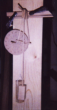
Sorry about the poor quality pictures, but all I had handy was a toy Polaroid camera. These scans came from pictures about the size of a postage stamp.
This is a Pin Wheel Escapement. See Mark Headrick's Pin Wheel Escapement animation page. The wood fall-weight is directly connected to a spindle behind the escape wheel. There is no gearing. The faces of the palettes are lubricated with powdered graphite.
 |
|
Links
The Clocks Site -- a great site by Carlo G. Croce
Marc Tovar's Wooden ClockWorks -- scroll saw plans
Melchester -- skeleton clock
Delightful Machines -- articles on mechanical movements
ClustrMaps
http://www3.clustrmaps.com/stats/maps-no_clusters/www.noah.org-thumb.jpg
