How Streams of Water Can Be Used to Create Analogues of Electronic Tubes and Circuits
---------------------
by C. L. Stong
August, 1962
---------------------
![]() EXPERIMENTERS
AND PHYSICS TEACHERS traditionally use mechanical models as aids in making
abstract concepts concrete. Direct electric current, for example, is often
seen in the mind's eye as water flowing through a pipe Alternating current
can similarly be visualized as the cyclic flow of water in a loop of pipe
attached to a cylinder fitted with a double-acting piston. Few experimenters
or teachers actually reduce such analogies to hardware. Even fewer develop
analogues in the absence of an immediate need. Why fiddle away time on
purposeless gadgets, real or fancied? One interesting reason is suggested
by the experience of Murray O. Meetze, Jr., a high school student in Heath
Springs, S.C.
EXPERIMENTERS
AND PHYSICS TEACHERS traditionally use mechanical models as aids in making
abstract concepts concrete. Direct electric current, for example, is often
seen in the mind's eye as water flowing through a pipe Alternating current
can similarly be visualized as the cyclic flow of water in a loop of pipe
attached to a cylinder fitted with a double-acting piston. Few experimenters
or teachers actually reduce such analogies to hardware. Even fewer develop
analogues in the absence of an immediate need. Why fiddle away time on
purposeless gadgets, real or fancied? One interesting reason is suggested
by the experience of Murray O. Meetze, Jr., a high school student in Heath
Springs, S.C.
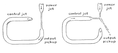 Figure 1: Pure fluid oscillator |
Meetze set out to devise an improved analogue of the triode vacuum tube. Although triodes have no moving parts, all triode analogues he had encountered (or that have come to my attention) consist of assemblages of motor-driven pumps, valves, tanks and pipes, or of such imaginary arrangements as air guns that shoot pellets at fluttering Venetian blinds. Meetze sought a working model in which nothing moved except a fluid representing the electric current. He not only designed and built such a model but also used it in a series of experiments that led to the construction of a fluid diode, a fluid oscillator and a variety of hydraulic "circuits," including one that has no electronic counterpart. As a result he was invited to the National Science Fair, held this year at the Seattle Century 21 Exposition. There his project won an award.
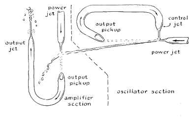 Figure 2: Pure fluid oscillator-amplifier |
Meetze writes: "A substantial number of pure fluid amplifiers have been devised. Most of them consist of channels or holes in blocks of metal, plastic or ceramic, depending on the application. The technology of designing pure hydraulic circuits was announced a few years ago by the Army's Diamond Ordnance Fuze Laboratories, but most of the work is classified. To qualify as a pure fluid device a design must have no moving parts. The hydraulic ram does not qualify, because it requires a pair of flap or ball valves, nor does the automatic clothes washer, because its cycles are governed by valves actuated by electric or hydraulic motors. The active elements of my circuits consist of nozzles and the passive elements of tubes and chambers. The pure fluid analogue of the triode vacuum tube, for example, is an arrangement of three nozzles. A jet of water issuing under a head of pressure from one nozzle corresponds to the evaporation of electrons from a heated cathode; the pressure corresponds to the electric potential set up by the B battery. A second nozzle pointing toward the first nozzle receives the jet and corresponds to the plate of the triode. A third nozzle located in the plane of the first two but at right angles to the jet functions as the grid of the triode. In the absence of a jet from the control (grid) nozzle, water flows from the power (cathode) nozzle and enters the output (plate) nozzle. Because the nozzles are located in the same plane, a jet issuing from the control nozzle collides with the jet from the power nozzle and diverts it away from the output nozzle, thus interrupting the transfer of fluid between the power and output nozzles. This action is analogous to the effect of a negatively charged grid on the plate current of a vacuum tube. A pure fluid triode connected for operation as an oscillator is shown in the accompanying illustration. Here the conducting phase is at the left and the nonconducting phase at the right.
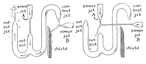 Figure 3: Asymmetrical flip-flop |
"The operation of a pure fluid oscillator is much easier to grasp than its electronic analogue. Water entering the power nozzle under pressure and flowing from it as a jet is received by the output nozzle and fed back through circuit tubing to the control nozzle. The resulting jet from the control nozzle momentarily deflects the power jet away from the output nozzle. The action is not instantaneous. Initially the control circuit is empty and a little time is needed for it to fill up. Even a full control tubing contains a few bubbles of air that must be compressed before the jet forms. The springiness of the bubbles corresponds to capacitance in the electrical analogue. In addition, the column of water in the control circuit has mass and is therefore characterized by inertia. The column cannot be instantaneously accelerated from rest to maximum velocity. The inertia corresponds to electrical inductance. As a result the power jet flows into the output jet for a finite interval and is then diverted for another finite interval, depending partly on the momentum of the control stream and partly on the energy stored in the compressed bubbles. The cycle is then repeated. The output consists of a series of unidirectional pulses, as does the output of a triode oscillator. I have not attempted to couple the oscillator to a 'tank' circuit for converting the unidirectional pulses into alternating flow. Such a tank might consist of a U-shaped tube. The output of the pure fluid oscillator would be fed into one arm of the U. Periodic pulses of incoming water would make water standing in the U tube oscillate at a frequency determined by the 'inductance' represented by the mass of the water column and the 'capacitance,' in this case represented by the force of gravity.
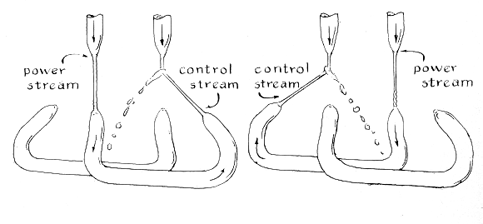 Figure 4: Symmetrical flip-flop |
"When these experiments were first undertaken, I spent a lot of time trying to design completely enclosed systems. It seemed obvious that a jet of water could not possibly enter a facing nozzle without excessive splashing, particularly if it had to work against a head of pressure in the facing nozzle. One day I directed a small stream from one eyedropper nozzle into another nozzle about two inches away. The diameters of the nozzles were about equal. To my surprise the arrangement worked about as efficiently as a closed system. When the stream is laminar, the jet narrows somewhat as it comes from a nozzle. Hence it readily enters an opening with the same diameter as that of the exit nozzle. On entering the second nozzle the jet is capable of building up a head of pressure because of its momentum. The disadvantage of using a receiving nozzle with a diameter smaller than that of the exit nozzle is obvious. On the other hand, pressure will not develop in a receiving nozzle so large that the jet simply splashes off the inner wall and runs out.
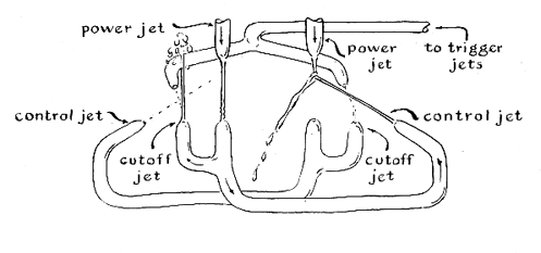 Figure 5: Positive-acting flip-flop |
"I use the glass parts of eye droppers for nozzles, the kind without the little glass bulb at the dropping end. Pairs of nozzles with apertures of matching size could be made by softening a short length of glass tubing at the middle in a gas fiame, removing the tubing from the flame and quickly pulling the ends apart. The narrow portion could then be nicked Iightly with a three-edged file and broken to form two nozzles of identical diameter. I connect the nozzles into circuits by means of transparent plastic tubing and interconnect sections of tubing with copper L's, T's and straight couplings as required. These details are omitted in the accompanying illustrations. The nozzles and associated tubing can be mounted on any firm support, such as an apparatus stand or a vertical grid made of wooden dowels. The tubing can be wired to the supports, but clamps of the thumbscrew type make adjustment easier. Glass parts should be slipped into a sleeve of rubber tubing for protection at points where they are clamped. A basin equipped with a drain must be provided to catch the spent water. Any watertight box with low sides will do. The experimenter can make one of wood easily. Mine is made of sheet metal with soldered corners.
"In the course of experimenting with the oscillator I found that the deflected power stream could be used to control another power stream. Thus an oscillator operating from a source of low pressure can exert direct control over a second triode operating from an independent power supply, as shown in the accompanying illustration [second from top at right]. Amplification is observed if the pressure of the second power supply is higher than that which drives the oscillator. A pinchcock of the screw type installed on the tubing of the second power supply will function as a 'volume' control. The action of the oscillator is entirely independent of the amplifier. The frequency remains constant at all settings of the volume control.
Figure 6: Pure fluid diode |
"While experimenting with the oscillator-amplifier circuit in an attempt to make a hydraulic motor control itself, I hit on a bi-stable circuit, an analogue of the electronic 'flip-flop.' In one of the two stable states a power jet drives a control jet that deflects a second power jet against a shield, as shown at the left in the accompanying illustration [Figure 3]. An output jet connected to the control circuit of the first power jet delivers output, in the form of a miniature fountain, as long as the circuit remains in this state. If you interrupt the first power jet, for instance by sticking your finger momentarily into the stream, the circuit flips to its alternate stable state. The second power jet deflects the first power jet from the control circuit. Interrupting the second power jet returns the circuit to its initial stable state. The switching intervals are approximately equal, although the circuit is asymmetrical.
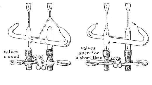 Figure 7: Negative-pulse flip-flop |
"After learning that electronic flip-flops are symmetrical I undertook the development of a symmetrical analogue. This proved to be rather easy: it is simply a pair of triodes cross-connected so that the output of one controls the input of the other and vice versa [Figure 4]. Observe that the control nozzles are directed upward toward the power jets from the same level as that of the output nozzles. This makes the circuit change state quickly when the operating power jet is interrupted, because water stands in the feedback tubes even when they are not conducting. The switching time can be increased (frequency lowered) by adding the analogue of capacitance to the control circuits. Just tip the feedback tubes so that the output nozzles are higher or lower than the control nozzles. The resulting bubbles in the control branches after each operating cycle will introduce delay.
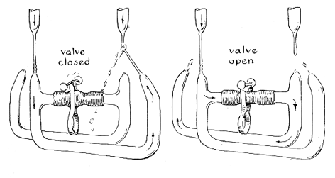 Figure 8: Single-trigger flip-flop |
"Both versions of the flip-flop were triggered, or flipped, by interrupting the power jet by hand. Electronic counterparts use a triggering circuit. My next series of experiments was aimed at developing a pure fluid analogue of the electronic trigger circuit. The problem appeared to be rather simple at first: a pair of triggering nozzles powered from a common source would be positioned so that jets of short duration could divert either the control jets or the power jets. The first triggering pulse would 'flip' the circuit for conduction by one stage; the following pulse would 'flop' conduction to the alternate stage. I decided to trigger the control jets. Experiment quickly showed that the problem was not so simple. At certain times the circuit flipped and at other times it remained in the initial state, depending on the duration of the triggering pulse. A sufficiently short pulse triggered a change in state every time. A long pulse would in effect trigger both the flip and the flop, because the twin jets of the trigger could divert either or both of the control jets. Positive action was provided by a second pair of jets located between the triggering jets and their corresponding control jets. These can be thought of as cutoff jets. Their location is shown in the accompanying illustration [Figure 5]. The cutoff jets block the triggering pulse on the conducting side and prevent its twin from hampering the action of the 'off' control jet. Observe that the output pickup nozzles, the control and cutoff nozzles are located on a common level to prevent the circuits from draining in the flipping interval.
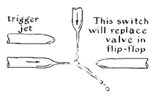 Figure 9: Pure fluid trigger |
"One can construct a variety of flip-flops, some that require diodes as their electronic counterparts do. Although these are interesting both as analogies and as experiments, they do not operate more effectively than the circuits described earlier. Diodes are interesting and simple to construct, but the nozzles must be almost perfectly matched and aligned or they will not operate reliably. Diodes consist of two nozzles, one aimed directly toward the other and the second canted slightly. In the accompanying illustration [Figure 6] conduction is shown at the left and nonconduction at the right. The sensitivity of the circuit to adjustment can be lowered somewhat by flaring the canted nozzle so that the tip resembles a miniature funnel. The flaring can be done easily with the aid of a special tool. Remove the carbon rod from a size C flashlight battery, insert it into the chuck of an electric drill and, with the drill running, file the uncapped end of the carbon to a tapered point. Then soften the glass tip in a gas flame, remove the glass from the flame, quickly insert the carbon point into the opening of the nozzle and spin the glass between finger and thumb until it cools. With a bit of practice it is possible to produce a symmetrical flare about an eighth of an inch long with an outer diameter about twice that of the bore of the nozzle. By blowing a small bulb in one side of the flared nozzle it should be possible to make a pure fluid analogue of the variable-capacitance diode and set up a parametric oscillator.
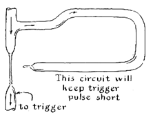 Figure 10: Short-pulse generator |
"While examining electronic circuits closely I concluded that triggering involves a negative pulse: taking energy away from the circuit rather than adding it. With this in mind I returned to the symmetrical bi-stable circuit and equipped the control feedbacks with drains in the form of pinchcocks placed so that they can be opened simultaneously, as shown in the accompanying illustration [Figure 7]. Operating the pinchcocks reduces the pressure of the conducting control jet but has no effect on the nonconducting branch. (Incidentally, it will be observed that when conduction is initiated in a circuit, the first pulse from a nozzle is much more forceful than that of the steady stream. The effect is explained by the momentum gathered by the water as it rushes through an empty tube; it is analogous to inductive effects in electronic circuits that generate pulses of high voltage, such as 'kick' coils and induction coils.) The initial circuit operated well enough to demonstrate that I was on the right track. The device is highly sensitive to input pressure at the power jets, however, and tended to go into uncontrolled oscillation rather than to flip.
"A variation of the arrangement resulted in my most effective flip-flop. Two feedback drains are coupled through a single-trigger valve, or pinchcock [Figure 8]. Opening the valve greatly decreases pressure at the presently conducting control jet, and the water drains into the presently nonconducting control jet. The 'off' power stream thereupon activates the 'off' control jet, completing the flip. The second operation of the valve returns the circuit to its initial state. Actually, even when the valve is opened momentarily, the circuit oscillates for a half-cycle. This constitutes the 'flip.' The circuit has one disadvantage: it is sensitive to variations in power pressure and tends to go into uncontrolled oscillation. The mechanical valve can be replaced by a pure fluid switch. One version is shown in the accompanying illustration [Figure 9]. Unwanted oscillation can be prevented by using triggering pulses of short duration. A circuit for generating short pulses automatically is assembled by coupling a cutoff nozzle to the triggering nozzle through a short length of feedback tubing [Figure 10].
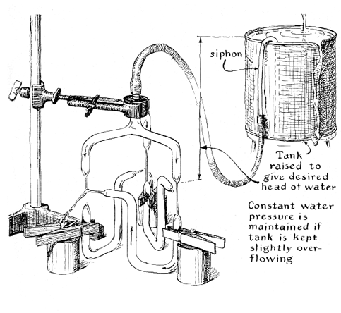 Figure 11: Three-phase oscillator |
"Pure fluid flip-flops can be ganged in series to make frequency dividers, binary counters and related devices used in digital computers. One output branch is tapped to trigger the succeeding flip-flop. The second branch functions as an indicator of state.
"Of the several devices that emerged from the experiments, one that seemed insignificant at first eventually gave me the most satisfaction because it led to a novel electronic circuit: a three-phase oscillator. In the case of simple flip-flops two pure fluid triodes are interconnected so that conduction in one blocks conduction in the other. When a third triode vice becomes unstable and oscillates. The arrangement is shown in the accompanying illustration [above]. Three power jets operate continuously. In the state illustrated the first control jet has cut off the second power jet. Accordingly the third control jet is also cut off. This enables the third power jet to activate the first control jet and, at the end of a time interval that depends on the constants of the system, to cut off the first power jet. As a result the jet action progresses around the ring at a phase angle, with respect to time, of 120 degrees. Further experiments demonstrated that triodes can be cascaded in this configuration without limit. Configurations containing any even number of triodes are stable and configurations containing any odd number oscillate.
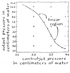 Figure 12: Graph of fluid amplification |
"There appears to be an electronic analogue for each of the pure fluid circuits and vice versa; any scheme should be transferable from one system to the other. The analogies are not perfect, however, and it is not always easy to devise an analogue even though a model representing one of the two systems is at hand. I have dreamed of constructing a pure fluid audio amplifier, for instance, ever since the experiments got under way. In contrast to the output signal of flip-flops and other all-or-nothing devices that in effect are little more than automatic switches, the amplitude of an amplifier's output signal must bear a constant proportional relation to amplitude of the input signal. Careful measurements indicate a region through which the pressure of the output circuit of a pure fluid triode varies directly with the pressure of the control jet. Although the gain in pressure is small in regions approaching complete conduction or nonconduction, it varies from sixfold to 20-fold between these extremes, depending on the pressure of the power jet, and is substantially linear. A curve of the characteristic gain can be drawn by plotting a series of simultaneous measurements of output pressure and control-jet pressure. My measurements are made in terms of centimeters of water head by means of a simple water manometer. The pressure of the power jet is maintained at constant value during the run. The accompanying graph is typical. With nozzles of optimum size output pressure approaches the pressure of the power supply within a few centimeters, in spite of the fact that the jets are not enclosed. A convenient setup for making simultaneous measurements is shown in the accompanying illustration [Figure 11]. Pressure of the control jet is varied by a pinchcock of the screw type. The control gauge and output gauge tubes are calibrated against a standard meter stick. The measurement is equivalent to plotting the grid voltage of a vacuum tube against plate voltage.
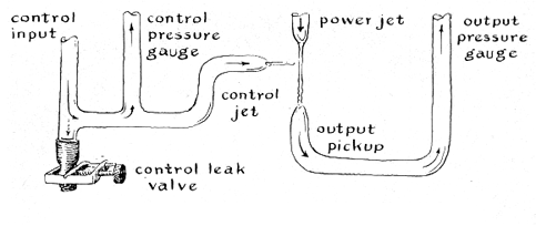 Figure 13: Apparatus for measuring characteristics of pure fluid amplifier |
"Pure fluid devices, like all experimental apparatus, are obedient to Murphy's law: If something can go wrong, it will. Success comes easiest when certain precautions are observed. Faulty operation is most often traced to air that is inadvertently trapped in one circuit or another. Usually the symptoms show up as unstable jets, or sputtering. Unwanted air often enters the circuit with the power jet, particularly when the power jet is misaligned or improperly designed. The use of glass tubing or transparent plastic tubing is recommended because streams of bubbles in circuits such as feedback loops are easy to see. Air can be trapped in any loop, particularly a loop that operates in a vertical plane, and this must be taken into account in the design of a circuit.
"Variations in the pressure of tap water can present problems when you are experimenting with the more sensitive devices. I solve this problem by drawing water from a small tank located about five feet above the apparatus. My tank was equipped with six outlet valves from an old gas stove. They were soldered around the base of a one-gallon antifreeze can; two short nipples of copper tubing soldered into the can about an inch from the top provided input and overflow connections. A siphon arrangement should work just as well, although perhaps not so conveniently.
"Amateurs who enjoy solving mechanical puzzles will find a stimulating field in the design and construction of these analogues. The application of pure fluid devices appears to be limited only by the imagination of the experimenter. The fluid is by no means confined to water. With some modification of nozzle configuration it should be possible to devise a triode that works on compressed air. We will probably never have the opportunity to listen to an air-driven stereo phonograph, but nothing in my experiments suggests that one cannot be built."
Suppliers and Organizations
Fry's Electronics retails over 30,000 electronic items within each store. Fry's has been keeping hi-tech professionals supplied with products representing the latest technology trends and advances in the personal computer marketplace for 15 years. Fry's has become the place where a technical customer can shop with confidence and comfort.
The Society for Amateur Scientists (SAS) is a nonprofit research and educational organization dedicated to helping people enrich their lives by following their passion to take part in scientific adventures of all kinds.
The Society for Amateur Scientists
5600 Post Road, #114-341
East Greenwich, RI 02818
Phone: 1-877-527-0382 voice/fax
Internet: http://www.sas.org/